
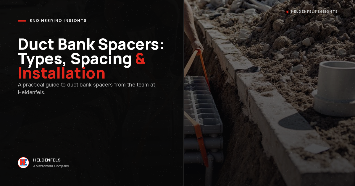
Duct Bank Spacers: Types, Spacing, and Proven Installation Best Practices
The cheapest component in the whole assembly is the one that decides whether your conduits hold their grid, shed heat, and stay put when six inches of concrete comes over the top. Here is how to specify and install them correctly.
On a bid sheet, duct bank spacers look like an afterthought. They are molded plastic, they cost a few dollars each, and nobody puts them in the project narrative. Then the trench gets poured, the concrete goes off, and the conduit grid inside is either exactly where the drawings said it would be or it is not. There is no second chance on an encased run. Every decision about spacer type, interval, and tie-down has to be made before the truck backs up, because once the pour starts the geometry is locked in for the service life of the structure. That is why we treat spacer layout as a quality control step rather than a hardware purchase, and it is the same discipline we apply to every element that leaves our yard.
In This Guide
What Duct Bank Spacers Actually Do
A spacer is a molded frame, usually high density polyethylene or polypropylene, that cradles each conduit at a fixed position in a grid. Set in a line down the trench, the frames turn a loose bundle of pipe into a rigid assembly. That assembly has to survive three separate loads: workers walking the trench, the hydraulic push of wet concrete arriving at several hundred pounds per cubic yard, and the buoyant uplift of empty pipe trying to swim to the surface.
The first job is geometry. Cable pulling calculations, splice locations, and every termination inside the manhole assume the conduits arrive in the pattern shown on the drawings. A run that drifts out of alignment mid-span turns a routine pull into a fight, and in the worst case forces a conduit to be abandoned.
The second job is thermal. Loaded power conduits generate heat, and heat that cannot escape into the surrounding earth reduces how much current the cable can safely carry. The spacing between conduits is the single largest variable you control on that front. The third job is concrete cover. The frames hold the outer conduits far enough off the trench walls and floor that encasement fully surrounds them rather than leaving a pipe kissing raw soil.
Base Spacers, Intermediate Spacers, and How They Interlock

Base units carry the stack and hold bottom cover; intermediate units clip on above them, one tier per conduit row.
Most duct bank spacers come in two pieces that are not interchangeable. Base spacers are the bottom tier. They have integral legs or feet that lift the entire grid off the trench floor, setting the bottom concrete cover, and they are built stouter because they carry the weight of everything stacked above them. Intermediate spacers clip into the tier below and add one more row of conduit each. Manufacturers key the two so an intermediate cannot be mistakenly used as a base, which is a small design detail that has saved a lot of crews from a very expensive mistake.
Sizing follows conduit trade size, so a run of 5-inch pipe needs 5-inch frames. Mixing trade sizes in one bank means either a mixed-size spacer product or a purpose-built arrangement, and that is worth resolving in submittals rather than in the trench at 6 a.m. A few practical distinctions to hold onto:
Base units set bottom cover
Their leg height is your bottom encasement dimension. Verify it against the detail before ordering, not after.
Intermediates add rows
Each tier adds one conduit row. Count tiers against the section detail so you order the right ratio.
Interlock is load path
Snapped connections transfer uplift down through the stack to the tie-downs. Unseated clips defeat the whole system.
Material matters in sun
Polymer frames staged for weeks in Texas heat can distort. Store them covered and inspect before setting.
Conduit Spacing, Heat Dissipation, and Ampacity
Here is the part that separates a code-compliant installation from an efficient one. Concrete is a better heat conductor than most soils, which is one reason encasement is favored for feeders, but a duct bank still forms a thermal block. Conduits in the middle of the grid sit surrounded by neighbors that are also generating heat, so they run hotter than the ones on the outside. Engineers call this mutual heating, and it is the reason a cable rated for one ampacity in free air carries less in a bank.
Standard practice for power runs is roughly 3 inches of clear separation between conduits, both horizontally and vertically, with about 3 inches of concrete cover around the outside of the bank. Widen that separation and each duct sheds heat into a larger volume of concrete and soil, which raises usable ampacity. Tighten it and you save trench width but pay for it in derating. Ampacity for encased duct banks is normally computed using the Neher-McGrath method or the published tables in the applicable industry standards, and the engineer of record makes that call under the framework of the National Electrical Code. What matters on the install side is simple: the spacer you order fixes that separation permanently, so it has to match the spacing the ampacity calculation assumed.
| Layout decision | Tighter spacing | Wider spacing |
|---|---|---|
| Cable ampacity | Greater mutual heating, more derating | Better heat dissipation, higher rating |
| Trench width | Narrower excavation and less spoil | Wider excavation and more restoration |
| Concrete volume | Less encasement per foot | More encasement per foot |
| Conductor size | May force an upsize to hit the load | Often supports a smaller conductor |
| Future capacity | Little thermal headroom for growth | Margin for added load later |
Communications and control ducts are a different conversation. They generate almost no heat, so their spacing is driven by separation from the power ducts and by pulling geometry rather than by thermal performance. Keeping the two groups apart in the grid, typically with power on the bottom tiers, is standard on the projects we support.
How Far Apart Along the Run?
Separation across the grid is one dimension. Interval down the trench is the other. Frames are commonly set every 5 to 10 feet, with 5 feet being the safe default for larger conduit and for any run that will be pushed hard during the pour. The governing question is conduit sag: PVC is flexible, and an unsupported span will belly downward under its own weight and under the load of fresh concrete, pinching your bottom cover and pulling the grid out of true. Tighten the interval at every bend, at both ends where the bank enters a manhole or stub-up, and anywhere the trench bottom is not uniformly bearing.
If you can push down on the assembled grid at mid-span and feel it move, the interval is too long. Add a frame. It costs less than a rejected pour.
Tie-Downs and Preventing Float During the Pour

Straps to driven stakes at every other frame, plus a partial first lift, are what keep empty pipe from floating out of position.
Float is the failure everyone has a story about. Wet concrete is dense, empty conduit is not, and the difference produces real uplift on the assembly. Duct bank spacers themselves do nothing to stop it. They hold the grid together while something else holds the grid down.
The standard remedy is mechanical restraint at regular intervals: stakes driven into the trench bottom, or anchors set in the mud slab, with straps or wire pulled over the top of the frames and tied off. Set them at least every other spacer and tighten them at bends, where uplift concentrates. Then control the placement itself. Pour in lifts rather than filling the trench in one shot, and let the first lift stiffen so it grips the lower conduits before the rest of the depth is placed. Keep the vibrator moderate and away from direct contact with the pipe, because aggressive consolidation both liquefies the mix around the assembly and can move conduit that was otherwise well secured.
Two more habits worth building. Cap or plug every conduit end before the pour so nothing enters the duct, and walk the run with a mandrel or proof line afterward so you learn about a problem while the crew is still mobilized rather than on the day the cable shows up.
Where Precast Quality Control Changes the Equation
Everything above describes a cast-in-place run, where the accuracy of the finished product depends on how well a crew holds tolerance in an open trench, in weather, on a schedule. That is achievable, and good electrical contractors do it every day. It is simply harder than doing the same work under a roof.
When the encasement is manufactured instead of poured in the ground, the variables collapse. Conduits are positioned against fixed jigs rather than measured off a trench wall. The grid is inspected before concrete is placed and verified again after stripping. Mixes are batched to a known volume, cured under controlled conditions, and the finished section is a documented piece with a known geometry rather than a buried assumption. Anyone who has watched how precast concrete is made in a plant recognizes the difference immediately: the same tolerance discipline that governs a bridge girder governs a conduit position.
That control is why precast concrete duct banks have become the preferred answer on projects where the schedule or the site will not tolerate a long open trench. Sections arrive complete, get set in sequence, and the trench closes behind the crew in a fraction of the time. On energy and industrial sites, including the LNG and regasified natural gas facilities we supply, that reduction in open excavation time is often the deciding factor all by itself.
Pre-Pour Checklist for Duct Bank Spacers
Run through this before the truck arrives. It takes ten minutes and it is the last moment anything can be corrected.
- Type and size confirmed. Base units on the bottom tier, intermediates above, all sized to the actual conduit trade size in the bank.
- Interval verified. Frames at the specified spacing, tightened at bends, ends, and any soft trench bottom.
- Grid matches the section detail. Conduit count, rows, and separation match the drawing the ampacity calculation was based on.
- Cover confirmed on all four sides. Bottom set by the base legs, sides and top measured against the trench and the finished elevation.
- Interlocks fully seated. Every clip snapped, no partial engagements anywhere in the stack.
- Tie-downs installed and tight. Restraint at least every other frame, doubled at bends and transitions.
- Ends capped and ground conductor placed. Nothing open to the pour, grounding installed per the design.
- Placement plan agreed. Lift depth, vibration limits, and who is watching the grid during the pour.
The Bottom Line
Duct bank spacers are cheap hardware doing expensive work. They set the geometry your cable pull depends on, the separation your ampacity calculation assumed, and the cover your encasement needs to actually protect the run. Get the type right, keep the interval short enough that nothing sags, and restrain the whole assembly against float before a single yard is placed.
And when the site cannot afford a long open trench or the tolerance stakes are high, consider moving the encasement into a plant where geometry is held to a jig instead of a tape measure. That is the same reason precast wins on so much of the rest of the structure.
Planning an Encased Electrical Run?
Our team has been engineering and manufacturing precast concrete in Texas since 1909, for highway, marine, industrial, and energy projects. Tell us what your run needs to carry and we will help you evaluate the options.
Explore Duct Bank Solutions