
Precast Concrete Beams: The Complete Expert Guide to Smart Engineering and Design
How engineers choose, specify, and size precast concrete beams, from the first span-to-depth estimate to the stress checks that happen long before a beam ever carries traffic.
Picture a county road crossing a creek. The old bridge is worn out, the replacement needs to span about 60 feet, and the road profile can’t be raised more than a few inches without rebuilding the approaches. That single constraint, how deep the structure is allowed to be, often decides which precast concrete beams make sense before anyone runs a full design. From there, the decisions follow a familiar order: beam type, the specifications that matter, load checks at every stage of the beam’s life, and how the same thinking carries into commercial and residential work.
- Most structural precast beams are pretensioned: high-strength strands are stressed on a casting bed, concrete is placed around them, and the strands are released once the concrete reaches its required release strength.
- Beam shape follows span and depth limits. Slab beams handle short spans, box beams cover short to medium spans with shallow depth, and I-girders reach the longest spans.
- A precast beam is checked at release, lifting, shipping, erection, and service, not only under the final design load.
- Camber, hauling routes, crane reach, and connection details are design inputs, not afterthoughts.
- Bringing the precaster in during schematic design usually produces a lighter, faster, more economical structure.
What Sets Precast Concrete Beams Apart
A precast beam is cast in a plant, cured under controlled conditions, inspected, and then shipped to the site ready to set. Most structural beams are also prestressed. In a pretensioned beam, steel strands are stretched between abutments at each end of a long casting bed, the concrete is placed and cured, and the strands are cut once the concrete is strong enough. The strands try to shorten, the bond grips the concrete, and the beam is squeezed into compression before any outside load arrives.
That built-in compression does two jobs. It offsets the tension that bending creates in the bottom of the beam, which keeps cracking under control, and it lets a shallower section carry a longer span. Because the strands sit low in the section, release also bows the beam upward slightly. That upward bow is called camber, and it comes back later in design and erection. For a comparison with conventional rebar-only members, see our breakdown of prestressed versus reinforced concrete beams, and for the production sequence itself, our step-by-step look at how precast concrete is made.
Common Types of Precast Concrete Beams and Where Each Fits
Every precast shape is a different answer to the same question: how much load, over how much span, within how much depth? The cross-section is where the engineering shows.
Slab Beams
Slab beams are shallow, wide, rectangular members used where spans are short and depth is at a premium. They set side by side to form a flat structural surface quickly, with minimal grouting and field adjustment. Our precast slab beams are built with precision-cast bearing surfaces and embedded plates, which is why they go together fast on commercial and industrial floor and roof systems.
Box Beams
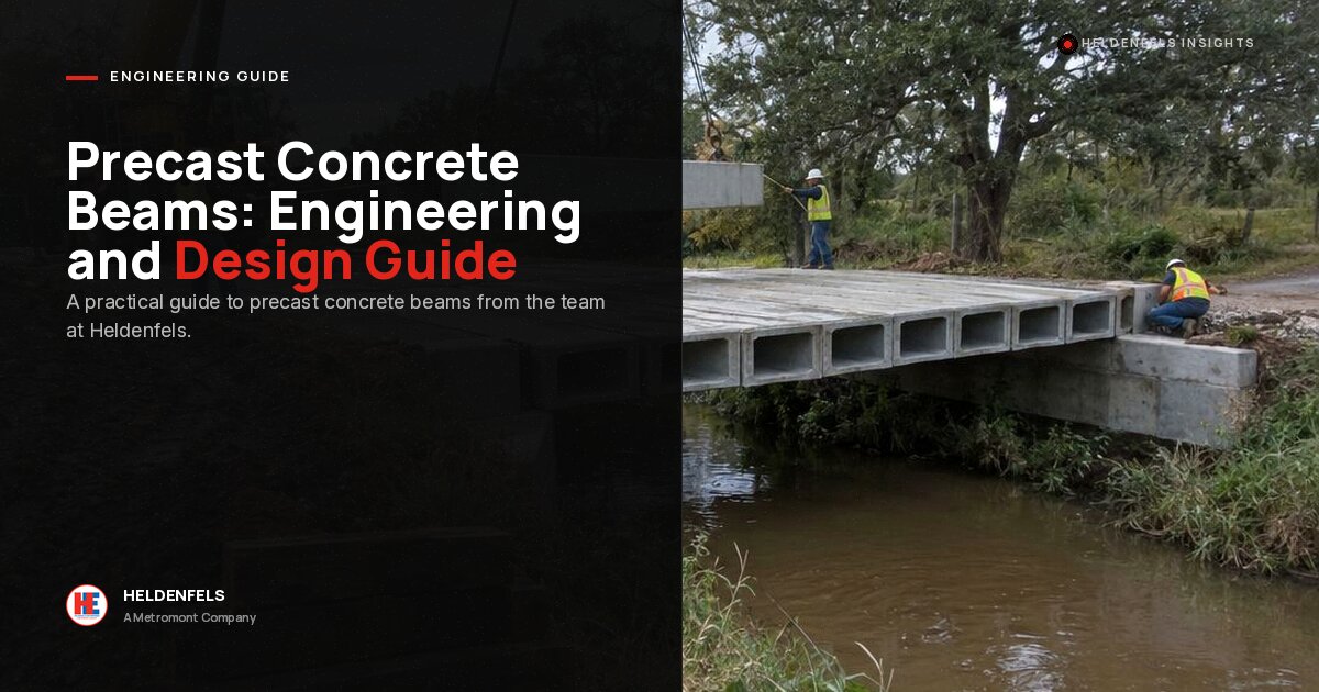
A box beam is a hollow rectangular section. The internal void removes concrete that contributes little to strength, so the beam stays light for its depth. Box beams are typically placed side by side, joined by grouted shear keys and often tied together transversely, so the tops of the beams form the riding surface or the base for a thin overlay. That’s why they suit the creek crossing: prestressed box beams carry short to medium spans at a shallow depth, with a clean underside and no deck forming over the water.
I-Girders and Bulb Tees
For longer spans, an I-shaped section puts concrete where bending stress is highest: in the top flange and the bottom flange (or bulb), connected by a thin web. A cast-in-place deck on top acts compositely with the girder. They are the standard choice for highway overpasses and river crossings, since they reach long clear spans and reduce the number of piers.
Building Beams: Inverted Tees, L-Beams, and Rectangular Beams
In parking structures and precast buildings, beams usually carry other precast members. An inverted tee has a ledge on each side that supports double tees or hollow core planks, while an L-beam has a single ledge for edge conditions. Rectangular beams handle simpler framing and transfer loads.
| Beam Type | Typical Role | General Span Range |
|---|---|---|
| Slab beam | Short spans, minimal depth | Short (roughly 20 to 50 ft) |
| Box beam | Short to medium spans, shallow structure | Short to medium (roughly 30 to 100+ ft) |
| I-girder / bulb tee | Long clear spans with composite deck | Medium to long (roughly 60 to 150+ ft) |
| Inverted tee / L-beam | Supports floor members in buildings and garages | Set by column grid and floor loads |
Treat these ranges as starting points. Actual limits depend on section depth, strand pattern, concrete strength, loading, spacing, and project specifications.
Key Specifications Engineers Set
Beyond dimensions, a precast beam drawing sets the specifications that drive performance and cost:
- Concrete strength. Plant mixes for prestressed work commonly reach design strengths of 6,000 to 10,000 psi, with a separately specified release strength the concrete must hit before strands are cut.
- Prestressing strand. Seven-wire, low-relaxation strand (commonly 0.5 or 0.6 inch diameter, Grade 270) is standard. The engineer sets the number, pattern, and jacking force.
- Strand debonding or draping. Near the beam ends, self-weight moment is small, so full prestress can overstress the top. Sheathing some strands or harping them upward controls those end stresses.
- Cover and durability. Coastal, marine, and deicing exposures call for more cover and low-permeability concrete. Plant curing helps deliver both consistently.
- Camber and tolerances. Predicted camber at release and at erection sets bearing seat elevations and deck haunch or topping thickness.
- Bearings and connections. Elastomeric pads, embedded plates, shear keys, and transverse ties determine how beams share load and move with temperature.
Load Calculations for Precast Concrete Beams
Sizing a precast beam starts with loads. On bridges, designers work with permanent loads (the beam, deck, barriers, and future overlay) and vehicular live load, which in AASHTO LRFD design is the HL-93 model: a design truck or design tandem combined with a uniform lane load. In buildings, dead and live loads follow ASCE 7 and the building code, with combinations such as 1.2 dead plus 1.6 live.
Load factors are applied by limit state. For a bridge beam, the Strength I combination factors component dead load at 1.25, wearing surface at 1.50, and live load at 1.75. Service limit states check stresses and cracking, and Service III specifically checks tension in prestressed members.
Every Stage Gets Its Own Check
Precast design is unusual in that the beam gets checked long before it carries traffic. At release, the concrete is at its youngest and the prestress is at its highest. During lifting, the beam hangs from pick points rather than its bearings. On the truck, it rides on supports that may sit inboard of the final bearings while it takes road bumps and cornering forces. Long, slender girders are also checked for lateral stability during lifting and hauling. Only then come the composite deck stage, final service, and strength.
A quick sizing example. Back at the 60-foot creek crossing, AASHTO’s traditional (optional) minimum-depth guidance for simple spans gives a fast first look: about 0.045 times the span for precast I-beams versus about 0.030 times the span for adjacent box beams. That works out to roughly 32 inches of structure for the I-girder option and roughly 22 inches for adjacent boxes.
Ten inches can be the difference between a road profile that works and one that forces new approaches. Next comes self-weight: a box section with about 4.5 square feet of net concrete area weighs roughly 0.675 kips per foot at 150 pounds per cubic foot. Using M = wL²/8, its self-weight moment at midspan is about 304 kip-feet before overlay, rails, or traffic are added. Final design always comes from the engineer of record.
Handling, Shipping, and Erection Shape the Design
A beam that can’t reach the site or be lifted by an available crane isn’t a viable design, no matter how good its stress checks look. Length, weight, and height drive permit requirements, escorts, night travel windows, and route surveys for tight ramps and turns. Very long girders often ride on specialized trailers with steerable rear dollies.

Camber matters here too. It continues to grow over time as the concrete creeps, so a beam stored for months may arrive with more camber than one shipped quickly. On girder bridges, a variable haunch under the deck absorbs camber and vertical curves. With adjacent box beams there’s no haunch to hide behind, so differential camber between neighboring beams has to be managed with leveling and topping. On a bridge sitting on a pronounced vertical curve, that correction can add meaningful dead load, which sometimes favors spread girders over adjacent units.
Erection planning belongs on the drawings early, too: crane size and pick radius, beam bracing until diaphragms or the deck are complete, and the sequence for grouting shear keys. The Federal Highway Administration’s guidance on accelerated bridge construction is worth reading for owners weighing prefabricated elements to shorten closures.
Commercial and Residential Applications
Bridges get most of the attention, but the same engineering applies across project types:
- Highway and transit bridges: girders and box beams for overpasses, interchanges, and stream crossings where long spans and short closures matter.
- Parking structures: inverted tees and L-beams carrying double tees over long, column-free bays.
- Commercial and industrial buildings: slab beams and rectangular beams for heavy floor loads, open floor plans, and fast enclosure.
- Multifamily and mixed-use residential: precast podium levels and garages beneath apartments, where fire resistance and speed help the wood or steel framing above start sooner.
- Private crossings: ranch, subdivision, and driveway bridges where a short-span box or slab beam is quicker to install than forming over a creek.
- Marine and industrial platforms: durable plant-cast members where exposure is harsh and field forming is impractical.
Bring the Precaster In Early
The most economical precast concrete beams are designed around how they will be made, shipped, and set. A few habits pay off:
- Standardize sections and lengths. Repeating the same shape lets a plant reuse forms across many pieces.
- Confirm hauling limits before locking spans. A small span adjustment can avoid a costly permit tier.
- Design connections with erection in mind. Simple, accessible details shorten crane time.
- Specify release strength and camber expectations clearly. These control production cycles and field elevations.
- Review shop drawings jointly. Embeds, lifting devices, and blockouts are far cheaper to fix on paper.
Groups such as the Precast/Prestressed Concrete Institute publish design manuals and plant certification standards that support this kind of coordination.
Engineering a Precast Beam Project?
With Texas roots dating to 1909 and prestressed concrete production going back to 1955, Heldenfels Enterprises manufactures and installs precast and prestressed concrete for projects across the state. Our team can help you compare beam types, test span and depth options, and plan production and delivery around your schedule.
Contact Us About Your Project