
Precast Concrete I Beams: The Complete Expert Guide to Load Capacity and Proven Design
Precast concrete I beams carry many of the medium and long spans on modern highway bridges. Their load capacity is built in at the plant and sized to the span by engineers, but the job is not done until they are set safely in the field.
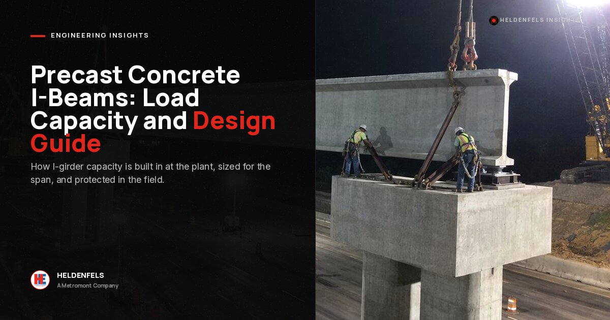
It is 2 a.m., the interstate below is closed, and two cranes are holding the first girder of a new span over a bent cap. That girder is one of the most vulnerable pieces on the job: about four feet deep, well over a hundred feet long, with no neighbors to lean on and no deck to stiffen it. The crew will not let the cranes go until it is braced. Precast concrete I beams get their strength in the plant, but how much of it they deliver depends on how they are lifted, shipped, braced, and tied into the deck.
- An I-beam puts concrete in the top and bottom flanges, where bending stresses are highest, and keeps the web thin to save weight.
- Most of its capacity comes from three sources: pretensioned strands set low in the bottom flange, high-strength plant concrete, and composite action with the cast-in-place deck.
- A girder carries thousands of kip-feet of its own weight and fresh deck before a single truck crosses, so the construction stages control much of the design.
- A common first-pass depth estimate for simple-span precast I-beams is about 0.045 times the span, measured to the top of the deck.
- One of the biggest installation risks is the first girder in a span. It must be braced before the crane releases it.
What Makes Precast Concrete I Beams Different
The difference between a precast beam and a cast-in-place (in situ) beam starts with where the concrete hardens. A cast-in-place beam is formed and poured at its final location, usually on falsework, and it either relies on conventional rebar or is post-tensioned after it cures. A precast I-beam is cast on a long steel bed at a plant, around high-strength steel strands that were stretched before any concrete was placed. Once the concrete reaches its release strength, the strands are cut. They try to shorten, the concrete grips them, and the beam is locked into compression before it ever leaves the yard.
The I shape makes that prestress efficient. Bending creates the highest stresses at the top and bottom of a section, so the I puts its mass there: a top flange to resist compression and a heavier bottom flange to house the strands. The thin web in between mainly carries shear. For a closer look at why prestressing beats rebar alone on long spans, see our comparison of prestressed and reinforced concrete beams.
How Load Capacity Is Built Into an I-Beam
The load capacity of a precast I-beam is really several capacities, checked at different points in its life. Three design levers drive all of them.
Strand Force and Eccentricity
The prestress force pushes along the strand centroid, which sits well below the girder’s own centroid. That offset, the eccentricity, creates a moment that bows the beam upward and puts the bottom fibers into compression. Service loads then have to cancel that compression before the bottom of the beam goes into tension. More strands, or strands set lower, mean more load before cracking. One key limit shows up at release: the top of the beam can crack in tension if the prestress overwhelms the girder’s light self-weight near the ends. That is why some strands are debonded (sheathed) or harped near the supports.
Concrete Strength
Plant mixes for prestressed girders commonly reach 6,000 to 10,000 psi, with a separate, lower release strength the concrete must hit before strands can be cut. Higher strength allows more prestress, and that buys either a longer span from the same section or wider girder spacing on the same span.
Composite Action With the Deck
Stirrups project out of the top flange and get embedded in the cast-in-place deck. Once the deck cures, girder and slab bend as one deeper section. The deck becomes a wide compression flange, and the stiffness of the section jumps. This is a major reason precast concrete I beams reach spans that would be impractical for a girder working alone.
A quick look at dead load. Take a standard AASHTO Type IV girder: 54 inches deep with about 789 square inches of concrete. At 150 pounds per cubic foot, it weighs about 0.82 kips per foot. On a 100-foot simple span, M = wL²/8 gives roughly 1,030 kip-feet of self-weight moment at midspan.
Add an 8-inch deck over 8-foot girder spacing, about 0.80 kips per foot of wet concrete, and the girder picks up roughly another 1,000 kip-feet before the deck has hardened and before any truck, barrier, or overlay. Live load under AASHTO’s HL-93 model comes after all of that. Final design always rests with the engineer of record.
Span Requirements and Spacing Tradeoffs
For a first estimate of depth, AASHTO’s traditional optional guidance for simple-span precast I-beams suggests an overall composite depth of about 0.045 times the span. For a 100-foot span, that is about 54 inches, girder and deck together. Treat it as a starting point, not a limit. Deeper sections, higher concrete strengths, and continuity over interior supports all change the answer.
| Span (simple) | 0.045 × Span | What That Usually Means |
|---|---|---|
| 80 ft | about 43 in | Shallower I-sections; box beams also compete here |
| 100 ft | about 54 in | Mid-depth I-girders with a composite deck |
| 130 ft | about 70 in | Deep I-girders or bulb tees; hauling becomes a design input |
Once depth is roughly set, spacing is the next lever. Wider spacing means fewer girder lines, fewer picks, and fewer bearings, but each girder carries more deck and live load, and the deck itself has to span farther between girders. Tighter spacing gives each girder an easier job but adds pieces to cast, ship, and set. The economical answer usually falls in the middle and depends on the plant’s forms, the crane, and the haul route.
Long, slender girders also bring stability into the span decision. A girder that works in final service can still roll laterally if it is lifted at the wrong points, rides a trailer with too much sweep, or stands unbraced in the wind. Our engineering guide to precast concrete beams covers how beam shape choices follow span and depth limits more broadly.
Installation Best Practices for Precast Concrete I Beams
Every capacity calculation assumes the girder arrives undamaged, sits on its bearings as drawn, and gets its deck in the intended sequence. The field work decides whether those assumptions hold.
Camber Is Measured, Not Assumed
Prestress bows a girder upward, and creep keeps increasing that camber while the girder sits in storage. Picture a girder predicted to carry 2.5 inches of camber at 60 days that ends up waiting about five months for its bridge. Before it ships, the crew stretches a string line from end to end and measures closer to 3.25 inches. That extra three-quarters of an inch comes straight out of the haunch at midspan. If nobody checks, the deck can end up too thin over the girder or the profile grade can bump up. Measuring camber at shipment and again after erection lets the contractor set deck screed elevations and haunch thickness from real numbers.

A Field Sequence That Protects the Girder
- Verify bearing seats before the girders arrive. Survey seat elevations, confirm bearing pad locations and orientation, and correct problems while the cap is still open.
- Lift only at the designed pick points. Lifting loops are placed so that handling stresses stay within what the section was checked for. Moving the pick changes the stresses.
- Brace the first girder before releasing the crane. Tie it to the cap or substructure with the specified temporary bracing. Each following girder is then braced to its neighbor as it is set.
- Respect wind limits. Long girders act like sails. Schedule picks for calm conditions and keep temporary bracing in place until diaphragms are complete.
- Place diaphragms and deck in the specified sequence. Uneven deck placement can twist girders and load bearings in ways the design did not anticipate.
Owners trying to cut lane closures should also read the Federal Highway Administration’s resources on accelerated bridge construction, which cover how prefabricated bridge elements help shorten traffic impacts.
When an I-Beam Is Not the Right Shape
I-girders are built for medium and long spans with a cast-in-place deck. Where vertical clearance is tight and spans are short, precast slab beams deliver a flat, shallow structure with minimal field work. Where spans run short to medium and the road profile cannot rise, prestressed box beams set side by side give a shallow superstructure with a clean underside and no deck forming over water or traffic. The right choice comes from the span, the depth budget, and how the structure will be built, not from habit.
Industry design manuals from groups like the Precast/Prestressed Concrete Institute lay out standard sections, handling checks, and production tolerances in detail. They are worth keeping close when sizing any girder.
Planning a Bridge With Precast Concrete I Beams?
With Texas roots dating to 1909 and prestressed concrete production going back to 1955, Heldenfels Enterprises manufactures and installs precast, prestressed concrete for bridge and infrastructure projects across Texas from our plants in San Marcos and Corpus Christi. Our team can help you compare girder depths and spacing, plan camber and shipping, and coordinate production with your erection schedule.
Contact Us About Your Project